Energy changes form.
Hydraulic energy drives the turbine. The generator produces electricity; a load converts it into heat and, for a laser, light. Losses occur throughout. This is energy conversion, not energy creation.
Open build guide · Version 2 · 4 November 2026
Follow the water. Trace the energy. Test the question. A practical system layout and research guide for understanding the water–turbine–laser experiment.
Illustrated system plan · Component-dependent design
01 · The system plan
Water passes through the turbine and leaves through the outlet. Adjusting the water flow changes the hydraulic input available to the turbine and therefore the generator’s electrical operating point. The generator converts mechanical energy into electricity, which supplies an external load. In the laser experiment, that load powers a laser located outside the water path.
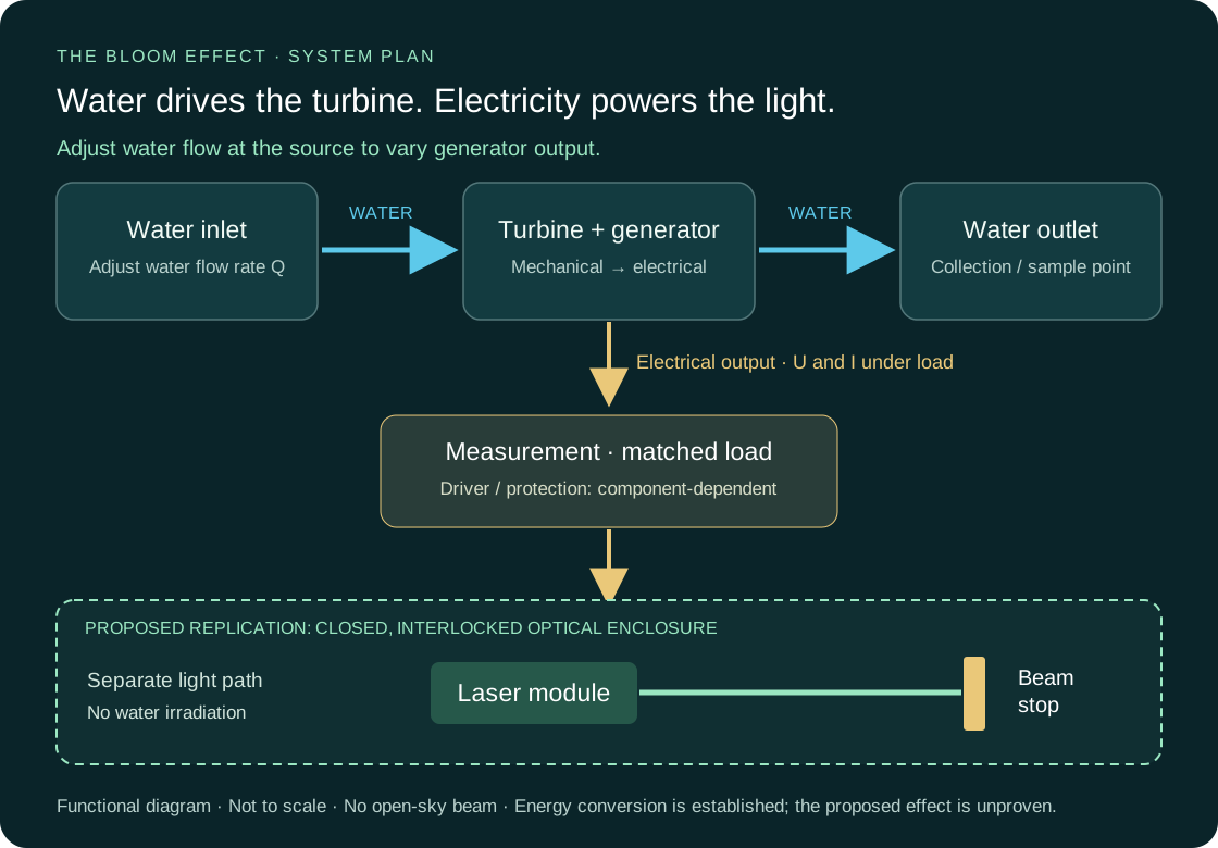
This is a functional build plan, not a pin-level wiring schematic. Connector pinouts, regulation, driver settings and protection values depend on the actual components and must be checked against their datasheets. A nominal “5 V” module does not establish compatibility with a generator.
02 · Theory & hypothesis
Hydraulic energy drives the turbine. The generator produces electricity; a load converts it into heat and, for a laser, light. Losses occur throughout. This is energy conversion, not energy creation.
Local structure can persist in systems exchanging energy and matter while total entropy increases. This principle alone does not predict an ordering effect in water passing through this device.
The Bloom Effect asks whether the way energy leaves the apparatus is associated with reproducible changes in water measurements. A causal connection beyond ordinary mechanical, thermal or electrical effects has not been demonstrated.
Hydraulic input: P ≈ Δp × Q
Electrical output: P = U × I
Use pressure difference Δp in pascals and flow Q in m³/s to obtain watts. Measure voltage U and current I under the same load. Optical output requires a suitable optical power meter; electrical input is not optical power.
Shorter wavelength means higher energy per photon (E = hc/λ). It does not by itself imply greater total optical power, greater water complexity or a stronger “Bloom Effect”. Crystal appearance alone is not a measurement of thermodynamic entropy.
Read the hypothesis →03 · Components
Begin with a low-voltage LED or resistor to demonstrate conversion and measure the generator. This tests the apparatus, not the proposed laser effect.
| Component | Purpose & selection |
|---|---|
| Water supply & tubing | A controlled water source, compatible hose, secure fittings, a valve and a collection vessel. Respect the turbine’s pressure rating. |
| Micro turbine with generator | A water-driven generator with documented voltage, current and pressure limits. Select the remaining parts from its measured output under load. |
| Electrical load & protection | For the first build: a suitably rated resistor or LED with its driver. Use insulated connections and protection selected for the actual components. Adjust generation through the water flow; a separate electrical switch is not part of the founder’s reported setup. |
| Measurement equipment | A multimeter, a flow measurement method (collected volume divided by time), a thermometer and a timer. Measure current in series, voltage in parallel. |
| Research laser branch | Only for appropriately trained operators: a specified laser module with its matched driver, supply regulation and a professionally assessed enclosure with interlocks and a rated beam stop. |
| Sampling materials | Identical clean containers, coded labels and a written protocol. Keep collection, storage and analysis conditions consistent. |
04 · Assembly sequence
Secure the inlet, turbine and outlet above a collection vessel. Keep the electrical section dry and separated from splashes. Check fittings and leaks with the electrical load disconnected.
Use the water-source control to vary the flow through the turbine and observe the generator voltage with a multimeter. Characterise changes using a suitably rated test load before considering a laser connection. Measure voltage and current under the same load; do not assume that the output changes in a fixed proportion to flow. Stay within component limits. Never put a meter in current mode directly across the generator terminals.
With water and power off, connect the protected output to a rated resistor or an LED driver and LED according to their datasheets. Inspect connections, restart the water and log loaded voltage, current, flow and temperature.
A trained operator must select and validate the matched laser driver, regulation and safety controls. Keep the complete beam path enclosed and terminated at a suitable beam stop. Do not substitute a bare laser diode for an LED or connect it directly to an unregulated generator.
Document component models, wiring, load, measured conditions, sampling location and timing. Photograph the setup. A changed load can change generator torque and the turbine’s operating point, so hydraulic conditions must be checked in every condition.
05 · A test that others can assess
Specify whether the generator is open-circuit or connected to a load. These are different operating conditions.
Use a rated non-laser load adjusted to a comparable electrical operating point. Record both electrical and hydraulic differences; matching input power alone does not eliminate every confounder.
Document colour, wavelength, optical output, driver and enclosure. Keep sampling conditions consistent. Add untreated water as a separate reference when appropriate.
Before running the experiment, define the primary outcome, sample count, exclusion rules and analysis method. Randomise the condition order, use coded samples with blinded analysis and repeat across independent runs. Record flow, pressure where available, temperature, duration, voltage and current for each condition.
Publish all images and measurements, including unchanged or contradictory results. For crystal photographs, standardise freezing and imaging, define image selection and scoring in advance, and seek independent replication. A visually striking image is not by itself evidence of a new physical effect or a health benefit.
06 · Original records & further reading
The procedure above is a proposed replication framework, not a transcription of the historical protocols. Use the original records for what was actually done.